Showing posts with label Software Diagrams. Show all posts
Monday, May 17, 2010

Medical Expert System Activity Diagram

To create an activity diagram for Medical expert system use cases.
PROCEDURE:

Medical Expert System Activity diagram first user enter there basic input details then it perform the verifying process if it is present then go to the process stage in these stage it do three action view , delete and Modify view the inpatient details. Delete it delete the inpatient details like that modify it perform the modification process to there database if it is not present then it will add inpatient details to there database Medical Expert System Activity Diagram

RESULT
Thus the activity diagram for medical experts system was drawn successfully in case tool lap with CS1403 Rational Rose Software

read more "Medical Expert System Activity Diagram"

Deployment Diagram Payroll Application Processing Management System

To draw the deployment diagram for the use-case, “Maintaining Employee Details”.Deployment diagram it has four blocks these are Ms-Access Manager login section and personal detail Manger section is divided the login and personal detail. By through pervious specification it will draw the Deployment diagram. In payroll processing activity diagram, component diagram, sequence diagram, usecae model by through these things you can generate uml diagram
Deployment Diagram Payroll Application Processing Management System

Thus the deployment diagram was drawn Rational rose case tool lap algorithm

read more "Deployment Diagram Payroll Application Processing Management System"

Payroll Application processing Management System Sequence Diagram Algorithm

To create a sequence diagram use case flow of events.
Payroll process sequence diagram it will perform three basic process function like personal IdetailForm() verification() store() . In there flow of the events show by the indicating arrow. Payroll sequence diagram we can get the clear view of the event process from the one object to the another.Traceability diagram it maintain employee details, sales details, report generator, employee details, sales details
Payroll Application processing Sequence Diagram Algorithm

Payroll APPLICATION processing Management System Traceability Diagram:
Payroll Application processing Sequence Diagram Algorithm Traceability Diagram Algorithm

Result :Thus the sequence diagram and Traceability Diagram was drawn CS1403 Rational Rose Software Rational rose diagram

read more "Payroll Application processing Management System Sequence Diagram Algorithm"

Class Diagram Online Flight Ticket Reservation System

To create a class diagram to show the classes and relationships that participates in the basic flow of the use-case, “Reservation Details”.
Procedure:1) Add the class diagram to the browser
a. Open the previous model.
b. Add the “Flight Details”, then class diagram under the use-case realization in the browser, and then open the diagram.
2) Add the classes to the diagram.
View the “Flight Details” collaboration diagram to determine the classes to add to the class diagram. Do not include actors in your class diagram. Actors exist outside the system.
3) Add associations.
Class Diagram Online Flight Ticket Reservation System

a. Use the collaboration diagram to determine the relationships between the classes
b. Look at the object links and the direction of communication.
c. From the diagram toolbar in the class diagram, check the unidirectional association icon and the drag the mouse from the sending class to the receiving class.
4) Add role names and multiplicity
Double click the association draw the entity class and the control class.
a. From the general tad type in the role A field and then click the role A detailed tab to add role A’s multiplicity from the multiplicity list, click 0..1 .
b. Click the role B detailed tab to add role B’s multiplicity from the multiplicity list, click 0...1 .
Try to add multiplicity between the boundary classes by right clicking the association.
Result:Thus a class diagram to show the classes and relationships that participates in the basic flow of use-case For Online Airway Ticket Reservation.

read more "Class Diagram Online Flight Ticket Reservation System"

Online Banking System Sequence Diagram For Bank Process Algorithm

To design the sequence and collaboration diagram for bank process algorithm using rational rose.
Description:Interaction diagrams are diagrams that described how groups of object collaborate to get the job done. Interaction diagrams capture the behaviour of a single use case, showing the pattern of interaction among objects. There are two kinds of interaction models. Online Banking System – Rational rose
(i) Sequence diagram
(i) Sequence Diagram Online Banking System:
Sequence diagram are an easy and intuitive way of describing the behavior of a system be viewing the interaction between the system and its environment. A sequence diagram shows an interaction arranged in a time sequence. It shows the object participating in the interaction by their life lines and the messages they exchange arranged in a time sequence.
A sequence diagram has 2 dimensions,
(i) Vertical dimension – represent time
(ii) Horizontal dimension – represents different objects
The Vertical line is called the object life line. The life line represents the object existence during the interaction. An object is shown as a box at the top of a dashed vertical line. Online Banking System
However, a sequence diagram does not show the relationship among the roles or the association among the object. An object role is shown as a vertical dashed line the life line. Internet Bank Software
Each message is represented by an arrow between the life line of two objects. The order in which these messages occur is shown top to bottom on the page. Each message is labeled with the message name. The label also can include the argument and some control information and show self delegation, a message that an object sends to itself by sending the message arrow bunch to the same lifeline. Internet Bank Software – Rational Rose
The horizontal ordering of the life line is arbitrary.
The sequence diagram is very simple and has immediate visual appear this is its great strength. Internet Bank Software
A sequence diagram is an alternative way to understand the overall flow of the control of the program. Instead of looking at the code and trying to find out the over all sequence of behavior we can use sequence diagram to quickly understand the sequence. Online Banking System – Rational rose diagram


Sequence Diagram Internet Bank Software
Online Banking System Sequence Diagram For Bank Process Algorithm

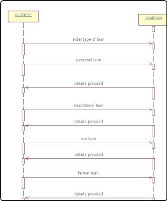
LOAN DETAILS: Internet Bank Software
Online Banking System Sequence Diagram Internet Bank Software Algorithm in c++

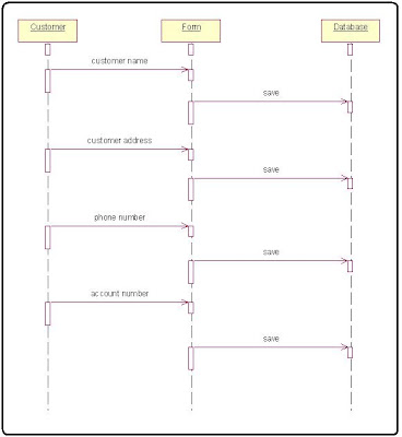
CUSTOMER DETAILS:
Online Banking System Sequence Diagram Internet Bank Software Algorithm in c++

CREATE A NEW ACCOUNT: Internet Bank Software
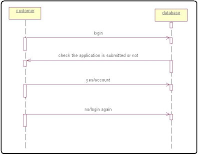
Online Banking System Sequence Diagram Internet Bank Software Algorithm in c++

CREATE A NEW ACCOUNT: Internet Bank Software
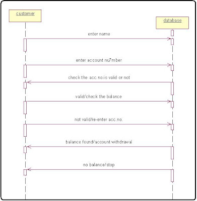
Online Banking System Sequence Diagram Internet Bank Software Algorithm in c++

CONCLUSION:Thus, the sequence and collaboration diagram for banking process was created.

read more "Online Banking System Sequence Diagram For Bank Process Algorithm"

Telephone Directory Use Case Diagram Problem Statement Identify Users Actor

To create a use case diagram for telephone directory
PROBLEM STATEMENT DESCRIPTION:
Telephone directory is the one, which contain details of an individual along with their landline numbers. Apart from the telephone number of individuals it also contain address and number of important institution like hospital, schools, police station and various organization belonging to particular district. It not only contains local codes but also ISD codes.
The names are present in alphabetical order so that one can easily find the required person along with their address and telephone numbers.Identifying actors and users Telephone Directory System problem description Statement

It also holds advertisement of some famous institution during times of enquiry.
We can depend on it entirely.
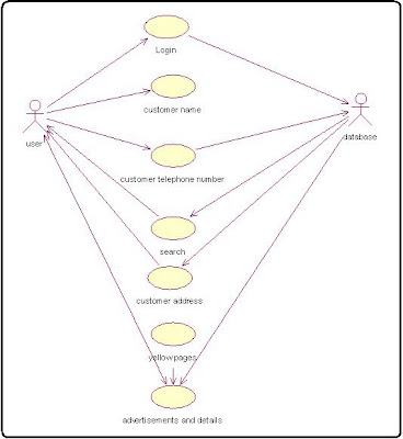
IDENTIFYING ACTOR AND USER:
1.User
2.Database
USECASE DETAILS:
1. Login.
2. Customer name.
3. Customer telephone number.
4.Customer address.
5.Yellow pages.
6.Advertisement details.
CONCLUSION:
Thus the usecase diagram for telephone directory was created successfully.

read more "Telephone Directory Use Case Diagram Problem Statement Identify Users Actor"
Friday, May 14, 2010

Library Management Class Diagram How to create Class diagram in Rational Rose

To draw the class diagram for library management system and to identify the attributes and methods of those classes.
CLASS DIAGRAM Library management Class diagram it has the following classes.
ABSTRACT CLASS Abstract class is represented using italic fonts.
CLASSES USED IN LIBRARY MANAGEMENT SYSTEM:
The classes are as follows
Student
BookClass Diagram Rational Rose Software for library Management
Finecalc
Issue
Return
Student:
It’s attributes are
Name
Regno
Studid
Branch
Address
It’s methods are
getdata()
disdata()
insert()
delete()
update()
Book:
It’s attributes are
Name
Author
Publisher
Price
Quantity
Accno
It’s methods are
getdata()
disdata()
insert()
delete()
update()
search()
Finecalc:
It’s attributes are
studid
accno
issue date
return date
amount
It’s methods are
check()
calc()
Issue:
It’s attributes are
studname
studid
studregno
bookname
accno
issuedate
returndate
author
It’s methods are
check()
entry()
price()
Return:
It’s attributes are
stud_name
stud_id
stud_regno
bookname
accno
issuedate
returndate
author
It’s methods are
check()
entry()
return()
CONCLUSION Thus the class diagram for library management system was constructed.
read more "Library Management Class Diagram How to create Class diagram in Rational Rose"

Flag counter

free counters